Report

Geophysics and Geophysical Exploration. 30 November 2025. 188-200
https://doi.org/10.7582/GGE.2025.28.4.188

ABSTRACT


MAIN

  • 서 론

  • 해상풍력단지 개발을 위한 지구물리탐사 국제 기준

  •   ISO (international organization for standardization)

  •   SUT (society for underwater technology)

  • 해양 지구물리탐사 방법에 따른 기술 사양 및 기준

  •   수심·지형 측량(정밀지형조사): 다중빔 음향측심기(multi beam echo sounder, MBES)

  •   해저면 특성(영상) 조사: 측면주사소나(side scan sonar, SSS) 및 해양 자력계(marine magnetometer)

  •   지층 구조 조사: 천부지층탐사(sub-bottom profiler, SBP) 및 초고해상도 탄성파탐사(ultra-high resolution seismic survey, UHR seismic survey)

  • 해상풍력단지개발 환경별 기술 사양

  •   고정식 해상풍력단지

  •   부유식 해상풍력단지

  • 해상풍력단지 개발을 위한 그라운드 모델링

  • 결 론

서 론

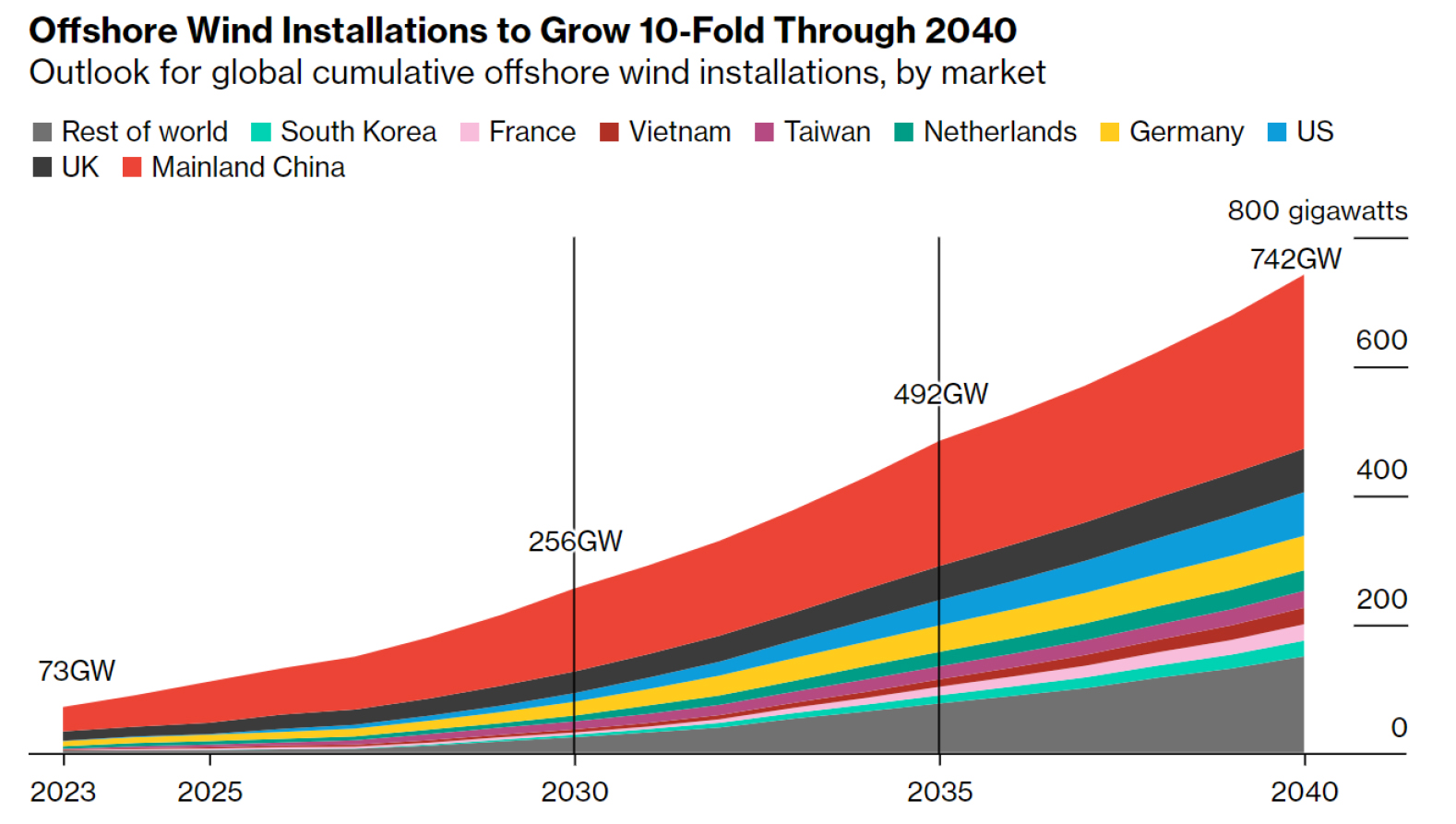
탄소중립 달성을 위해 2030년~2050년에 걸쳐 태양광 및 풍력 중심의 재생에너지 발전량이 크게 증가할 것으로 전망됨에 따라, 해상풍력 발전은 전 세계적으로 재생에너지 확대 전략의 핵심 축으로 자리매김하고 있다(International Energy Agency, 2024; DNV, 2024). 그 중 재생에너지가 전력 부문 탈탄소화에 크게 기여할 것으로 기대되면서, 탄소중립을 위한 해상풍력의 중요성이 확대되고 있다. BloombergNEF (2024)는 2024년 18.3 GW 규모의 해상풍력이 상업 가동될 것으로 예상하였으며, 2040년까지 누적 10배 가까이 성장할 것으로 전망하였다(Fig. 1).

https://cdn.apub.kr/journalsite/sites/ggekseg/2025-028-04/N0540280405/images/ggekseg_2025_284_188_F1.jpg
Fig. 1

Outlook for global cumulative offshore wind installations (BloombergNEF, 2024).

유럽을 비롯한 영국, 독일, 덴마크 등의 선진국을 중심으로 대규모 프로젝트가 활발히 진행되어 왔으며, 대표적으로 영국의 Hornsea Project와 네덜란드의 Gemini Wind Park, 독일의 Nordsee One과 Deutsche Bucht는 기술적·경제적 측면에서 해상풍력 산업의 가능성을 입증한 사례로 평가된다(Northland Power, 2020; Global Wind Energy Council, 2022). 중국, 대만, 일본 등 아시아 지역 또한 해상풍력 시장의 신흥 성장 축으로 주목받고 있다. 중국은 현재 세계 최대 해상풍력 시장으로, 2020년 기준 약 10 GW의 누적 설비 용량을 기록하며 공격적인 성장세를 보이고 있다(Chen and Lin, 2022). 대만은 2030년까지 13.1 GW, 2050년까지 40~55 GW 규모의 해상풍력 설치를 목표로 다양한 프로젝트를 추진 중이며, 일본의 경우 2030년까지 해상풍력 입찰 10 GW, 2040년까지 부유식 해상풍력발전을 포함하여 30~45 GW로 확대하는 정책을 전개하고 있다(Ministry of Economy, Trade and Industry, 2020; Chet, 2025). 미국의 경우, 아직 초기 단계에 있으나 버지니아 해상풍력단지 등 여러 프로젝트가 착수되면서 향후 시장 확대 가능성이 제시되고 있다(McCoy et al., 2024). 국내 해상풍력 산업의 경우, Fig. 2와 같이 새만금, 제주도, 서남해 등을 중심으로 해상풍력 프로젝트가 추진되고 있으며, 2030년까지 해상풍력발전 12 GW 준공을 목표로 개발을 추진하였다(Ministry of Trade, Industry and Energy, 2020) (Table 1). 2025년에 수립된 ‘제11차 전력수급기본계획(2024~2038)’에 따르면 주요 해상풍력 발전 추진 현황은 약 3.6 GW로, 2030년까지 14.3 GW 준공을 목표로 하고 있다(Ministry of Trade, Industry and Energy, 2025; Chae et al., 2025).
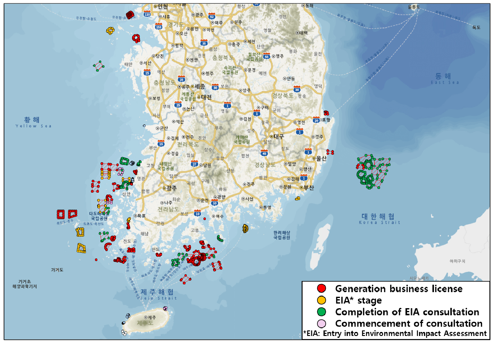
https://cdn.apub.kr/journalsite/sites/ggekseg/2025-028-04/N0540280405/images/ggekseg_2025_284_188_F2.jpg
Fig. 2

Distribution of Offshore Wind Farm Sites in Korea (modified from Energy and Space Co. offshore map (2025)).

Table 1

Status of Offshore Wind Farm Development in Korea (modified from Ministry of Trade, Industry and Energy, 2020; Ministry of Oceans and Fisheries, 2022).

Region Details
Jeonbuk–Southwest Sea Korea’s offshore wind development centered around the southwest sea: progressing through three phases—Testbed (Phase 1), Track Record (Phase 2), and Large-Scale Commercialization (Phase 3), aiming for a total capacity of 2.4 GW.
Sinan, Jeonnam Targeting a total of 8.2 GW: Phase 1 (4.1 GW, launched in 2021), with an additional 4.1 GW planned for Phases 2 and 3 (starting from 2026).
Ulsan & Southeast Focused on floating offshore wind using existing offshore gas infrastructure: 1.4 GW in Ulsan and 4.6 GW in the broader southeast region.
Others 0.6 GW in Jeju, 0.6 GW in Incheon, and other various locations.

해상풍력단지의 설계와 구축 과정에서 해저 지반에 대한 정밀한 이해는 구조물의 안정성과 장기 운영을 위한 핵심 요소로 작용한다. 그중 해상풍력 구조물은 극한 해양환경 속에서 수십 년간 안정적으로 운영되어야 하므로, 지반의 역학적 안정성과 해저 지질 구조에 대한 정밀한 조사가 필수적이다. 특히 해상 구조물의 기초 설계에는 해저 지층의 구성, 기반암의 깊이, 연약 지반의 분포, 단층 및 불연속면 존재 여부 등 다양한 지질학적·지구물리학적 정보가 요구된다(Yun et al., 2011). 이에 따라 해양 지구물리탐사는 풍력단지 조성의 초기 타당성 조사부터 상세 설계에 이르기까지 전 주기에 걸쳐 핵심적인 역할을 수행한다. 그 중에서도 해양 탄성파 탐사는 해저 지층의 연속성, 연약 지반 분포, 기반암 심도, 단층 및 파쇄대 존재 여부 등을 고해상도로 규명할 수 있어, 기초 설계의 적합성과 시공 리스크 평가에 필수적인 정보를 제공한다(Lee et al., 2019). 해외 주요국들은 이러한 해양 지구물리탐사의 중요성을 반영하여, 프로젝트 수행을 위한 세부 기술 기준과 조사 지침을 국가 단위 또는 산업 표준 형태로 마련하고 있다(International Energy Agency, 2023; DNV, 2024). 반면, 국내에서는 해상풍력 지구물리탐사에 대한 일관된 기술 기준과 조사지침이 부재하며, 해상풍력 사업에서 수행된 지구물리탐사는 해외 의존도가 높은 것으로 보고된 바 있다(Carbon Trust, 2023). 이러한 상황은 향후 대규모 해상풍력단지 개발 과정에 있어 기술적, 행정적 장애 요인으로 작용하여 설계 및 입지 개발, 인허가 획득 등의 과정에서 일정 지연과 사업비 상승으로 이어질 수 있다(Ministry of Trade, Industry and Energy, 2025). 본 논문에서는 해상풍력 개발을 위한 해양 지구물리탐사의 기술적 필요성과 역할을 정리하고, 국외 주요 국가에서 활용 중인 해양 지구물리탐사 기법 및 탐사 장비 기준을 분석한다.

해상풍력단지 개발을 위한 지구물리탐사 국제 기준

해상풍력단지 개발을 위한 지구물리탐사에는 국제 기준과 산업 지침이 적용된다. 특히 ISO (international organization for standardization), IOGP/OGP (international association of oil & gas producers), SUT (society for underwater technology), OSIG (offshore site investigation and geotechnics) 등의 기관이 해양 구조물 기초 조사 및 해상풍력단지 개발 관련 기준을 제시하고 있다. IOGP는 HSE (health, safety, and environment) 관련사항을 전문적으로 다루는 기관이자, 석유 및 가스 회사 협회로서 과학적 연구결과, 기준, 지침 등을 제시하였다. SUT는 국제 비영리 학술기관으로 해양 자원 탐사 및 활용, 환경 보호, 해저 인프라 구축 등의 분야에서 지식 교류와 기술 표준화를 수행하였다. 특히 해저 지반조사, 수중 구조물 설계, 해양 구조물의 설치 및 유지관리 등의 가이드라인을 제시하였다.

ISO (international organization for standardization)

ISO는 19,000개 이상의 국제 기준을 발표한 국제기구로서, 해양풍력단지 개발 및 조사를 위한 기준으로 활용되고 있다. 특히 해상풍력단지 개발 및 조사 ISO 국제 기준은 ISO 19901-10:2021, ISO 19901-8:2014에서 언급된 기준으로 활용되고 있다(ISO, 2014; ISO, 2021) (Table 2, 3). Table 2는 해상풍력단지 기초 설계를 위한 지구물리탐사 지침이며, Table 3은 지반 평가를 위한 지침을 나타낸다. 이는 풍력터빈과 같은 해양 구조물의 기반 설계 및 위험 분석에 대한 기술적 지침을 나타내며, 지반 특성 파악, 암반심도 추정, 지질 경계 정의, 매장 구조물/장애물 탐지, 지반위험 평가, 설계 입력 확보를 포함하고 있다. 또한, 탐사 전 연구(desk study)를 포함하여, 해저면(seafloor) 및 해저하부(sub-seafloor)의 공간적·물리적 특성, 지질재해(geohazard) 요소 파악을 포함한다. 적용 대상 수심 범위는 얕은 연안지역부터 최대 3,000 m 이상의 심해까지 해당되며, 그라운드 모델(ground model) 구축을 통해 해양 구조물 설치에 필요한 지반정보를 체계적으로 구성한다.

Table 2

ISO 19901-10:2021 (ISO, 2021).

Category ISO Standard
Application Target Geophysical surveys for foundation design of offshore structures
Recommended Equipment MBES, SSS, SBP, Magnetometer, MC-UHRS, etc.
Spatial Resolution Standard Horizontal: ≤0.3–1 m; Vertical: ≤0.25 m
Maximum Survey Depth SBP: ~10 m, MC-UHRS: ~100 m (below seabed)
Minimum Detectable Seafloor Feature Length/Width ≥1.0 m, Height ≥0.25 m
Data Format SEG-Y, ASCII, GeoTIFF, etc.
Coordinate/Depth Reference WGS84/ETRS89; water depth adjusted to VORF LAT reference system
Table 3

ISO 19901-8:2014 (ISO, 2014).

Category ISO Standard
Investigation Purpose Assessment of foundation soil stability, soil classification, and acquisition of design parameters
Investigation Method CPT, SPT, Vibrocore, Piston coring, Borehole, etc.
Soil Classification Standard Based on ISO 14688 and ISO 14689
Borehole Depth ≥20–100 m depending on structural load conditions
Index Tests Water content, density, grain size, plasticity, shear strength, undrained shear strength, etc.
Design-Relevant Parameters Allowable bearing capacity, settlement, liquefaction potential, soil-structure interaction analysis, etc.

IOGP (international association of oil & gas producers)

IOGP는 해양 석유 및 가스 산업에서 지구물리탐사를 위한 기준을 제공하고 있으며, 특히 위험요소 분석, 탐사 데이터 품질 확보, 환경 보호를 위한 기술적·운영적 지침들을 다루고 있다(International Association of Oil & Gas Producers, 2013). 특히 해양풍력단지 개발 및 조사를 위해 해저 지형·지질 위험 요소 식별, 설치 위치 안전성 검토를 목적으로 지구물리탐사분야에서 활용되고 있다. IOGP에서 제시하는 해양 지구물리탐사 조사 방법 및 기준은 Table 4와 같다.

Table 4
Category IOGP/OGP Standards
Survey Method High-resolution reflection seismic (2D/3D HR Seismic), side-scan sonar, multibeam echo sounder, magnetometer, etc.
Survey Depth Range Up to 100–150 m below the seabed (adjustable depending on project requirements)
Horizontal Resolution Resolution of ≥0.5 m accurate positioning required for analyzing structural/pipeline impacts
Maximum Survey Criteria Includes removal of mean drift, matching correction, depth adjustment, and interpretation of reflection boundaries
Data Quality Standard Requires sufficient signal-to-noise ratio (SNR), high spatial resolution, and full area coverage
Data Processing Must include mean drift removal, matching correction, depth alignment, and interpretation of reflectors
Geohazard Evaluation Requires classification of risk levels (Low/Moderate/High) and corresponding mitigation strategies

SUT (society for underwater technology)

SUT는 해양 지반공학 및 지구물리탐사 분야의 기술 표준 및 실무 지침을 제시하는 국제 기관으로, 해상풍력 등 해양 재생에너지 개발을 위한 기초 지반 조사를 위한 권고안을 발행하였다(Offshore Site Investigation and Geotechnics Committee, 2014). 특히 OSIG 위원회에서는 구조물 설계를 위한 기초조사에 있어서 해양 지구물리탐사의 역할과 장비 기준, 자료 해상도, 탐사 심도 등을 규정하였다(Offshore Site Investigation and Geotechnics Committee, 2014) (Table 5). 이는 해저면 및 천부 지층(수 m~수십 m)의 물리·공간적 특성 분석을 중심으로 하며, 기초 구조물 설계 뿐 아니라 해저 위험 요소의 사전 식별을 위한 탐사 설계 및 품질관리 기준(quality control, QC)을 포함한다. 조사 대상은 일반적으로 수심 수십 m의 고정식 풍력단지부터, 계류 시스템이 필요한 수심 수백 m 이상의 부유식 풍력단지를 포괄한다.

Table 5

SUT Guidance for Geophysical Investigations (Offshore Site Investigation and Geotechnics Committee, 2014).

Category SUT Standards
Application Target Geophysical investigations for offshore renewables (e.g., wind farms)
Recommended Equipment MBES, SSS, Magnetometer, SBP, UHR/MCS Seismic, ROV Imaging
Survey Objectives - Seafloor morphology and obstructions- Shallow stratigraphy and sub-seafloor features- Detection of UXO, pipelines, boulders, wrecks
Survey Resolution Standard Horizontal: ≤1 m Vertical: ≤0.25 m (for geohazard features)
Recommended Survey Depth SBP: 5–20 m, UHR Seismic: up to 100 m b.s.b (below seabed)
Minimum Detectable Object ≥0.25 m height, ≥1.0 m width
Data Format SEG-Y, XTF, GeoTIFF, etc.
Coordinate & Datum System WGS84; Positioning with DGPS and motion sensor corrections
Additional Requirements - 100% coverage of MBES/SSS- Integration with CPT/boring data for ground model- ROV imaging for visual QC when needed

해양 지구물리탐사 방법에 따른 기술 사양 및 기준

해상풍력단지 개발 시 기초 구조물의 규모와 형상은 수심, 지층 분포 및 지질학적 특성, 기반암 심도와 같은 지반 조건에 영향을 받는다(Yun et al., 2011). 이에 따라, 설계 및 시공에 필요한 지반공학적 기초자료를 확보하기 위해 해양 지구물리탐사가 활용된다. 특히 해상풍력단지의 경우 조사 범위가 광범위하므로, 조사 효율성을 높이기 위해 해양 지구물리탐사의 복합적인 기술들을 활용하여 해저 지형과 지질 정보를 수집한다. 주요 탐사 기법으로는 해저 지형 파악을 위한 수심 측량 및 지형 조사, 해저면 특성 조사를 위한 음향 이미지(해저면 영상조사) 및 자력 탐사, 해저지층 구조 파악을 위한 해양 탄성파 탐사 등이 있다. 각 기법은 상호보완적으로 활용되어 3차원적인 지반 모델 구축에 기여한다. 본 논문에서는 국제 기준 및 국내외 해상풍력 프로젝트에서 제시된 요구 조건을 기반으로, 주요 탐사기법의 기술 사양과 환경 조건에 따른 적용 기준을 정리하였다.

수심·지형 측량(정밀지형조사): 다중빔 음향측심기(multi beam echo sounder, MBES)

일반적으로 해저 지형과 수심을 정밀하게 파악하기 위해 다중빔 음향측심기(multibeam echo sounder, MBES)가 널리 사용된다. 다중빔 음향측심기는 선박이나 자율 무인잠수정(autonomous underwater vehicle, AUV)에 장착되어 여러 개의 음향빔을 부채꼴 형태로 해저에 발사하고, 반사 신호를 수신하여 고해상도 수심지형도를 생성하는 방식이다. 이 장비는 수심, 해저 경사, 수중 암초, 인공 구조물 등 잠재 위험 요소 식별에 필수적이며, 해상풍력단지의 기초 구조물 설계 및 케이블 경로 설정의 기초 자료로 활용된다. 다중빔 음향측심기는 전체 조사 구간에 대해 100% 커버리지(coverage) 확보가 원칙이며, 해상풍력단지 개발을 위한 수직 해상도는 ±0.25 m 이하, 수평 해상도는 1.0 m 이하가 요구된다. 이때, 해양 구조물의 위치 선정 및 위험도 분석을 위한 수심 측량 기준으로 IHO (international hydrographic organization)이 제시한 수심측량 표준이 적용된다(International Hydrographic Organization, 2020). 다중빔 음향측심기 해상도 요구사항으로 IHO S-44에서 제시된 Order 1a 등급을 충족하는 정밀도 확보가 필요하다(International Hydrographic Organization, 2020) (Table 6, 7). 실시간 수온 보정을 위해 CTD 센서가 필수적으로 사용되며, 측정값은 수직 해양 기준체계(vertical offshore reference frame, VORF)를 활용하여 최저 천문 조위(lowest astronomical tide, LAT)와 같은 해수면 기준으로 보정된다. 또한, 다중빔 음향측심기는 해저면 반사도(backscatter intensity)를 함께 기록하여 침전물 유형 분류 및 해저면 물리 특성 해석에도 활용할 수 있다. 얕은 수심이나 음영 지역, 항만 주변 등에서는 단일빔 음향측심기(single beam echo sounder, SBES)나 LiDAR 기반 수심계가 보조적으로 활용되며, 자율 무인잠수정에 탑재된 소형 다중빔 음향측심기 및 관성항법장치를 통해 인력 접근이 어려운 지역의 정밀 수심 조사가 가능해지고 있다. 이러한 수심·지형 측량 기술 발전은 해상풍력 부지의 디지털 지형 모델 구축을 가능하게 하였고, 설계 단계 뿐 아니라 시공, 운영, 유지관리 단계에서의 해저 지형 변화 모니터링까지 활용 범위를 확장시키고 있다.

Table 6

MBES minimum resolution requirements (Kongsberg, 2012; Corio, 2023).

Item Depth Requirement
Operating Frequency - 200-450 kHz
Positioning - -
Mobilization Testing and System Calibration - 1) Patch test following Industry Standard Guidelines
2) Distinct and recognizable object observed in data from 2 different survey location
Number of Sound Velocity Profiles - 12 per data minimum
Coverage <100 m As per IHO special order requirements
Minimum Horizontal Resolution <100 m 0.1 m
Minimum Vertical Resolution <100 m 0.1 m
Total Horizontal Uncertainty <100 m As per IHO special order requirements
Total Vertical Uncertainty <40 m As per IHO special order requirements
Sounding Density <40 m >12 hits per square metre
Total Vertical Uncertainty <60 m As per IHO special order requirements
Sounding Density <60 m >12 hits per square metre
Total Vertical Uncertainty <80 m As per IHO special order requirements
Sounding Density <80 m >9 hits per square metre
Total Vertical Uncertainty <100 m As per IHO special order requirements
Sounding Density <100 m >5 hits per square metre
Data deliverables <100 -
Table 7

Accuracy Orders for Hydrographic Surveys (International Hydrographic Organization, 2020).

Order Intended Use Depth Error
(95% CI, m)
Position Error
(95% CI, m)
Minimum Detectable
Feature Size (m)
Exclusive Order Exceptional applications requiring accuracy higher than Special Order, e.g., protection of critical infrastructure or defense purposes. 0.15 m + 0.0075 × Depth 1.0 m 0.5 m
Special Order Harbors, berthing areas, and areas critical for safe navigation where under-keel clearance is minimal. 0.25 m + 0.0075 × Depth 1.0 m 1.0 m
Order 1a High traffic coastal waters, anchorages, or areas for floating structure installation where precise depth is required. 0.5 m + 0.013 × Depth 2.0 m 2.0 m
(≤40 m, depth)
10% of depth
(>40 m, depth)
Order 1b General coastal surveys in areas where under-keel clearance is not critical and a full seafloor search is not required. 0.5 m + 0.013 × Depth 2.0 m N/A
Order 2 Deep-water surveys where safety of navigation does not require high accuracy. 1.0 m + 0.023 × Depth 5.0 m N/A

해저면 특성(영상) 조사: 측면주사소나(side scan sonar, SSS) 및 해양 자력계(marine magnetometer)

해저면의 퇴적물 표층의 분포와 특성을 파악하기 위해 측면주사소나(side scan sonar, SSS)는 필수적인 탐사 장비로 활용된다. 측면주사소나는 견인형 또는 자율 무인 플랫폼에 장착되어, 해저면을 향해 음향 펄스를 방사하고 후방산란 또는 반사된 음향 강도를 영상화하여, 해저의 반사체 분포와 퇴적물 정보를 시각적으로 제공한다. 이를 통해 암반, 어망, 난파선과 같은 수중 장애물, 인공구조물 등의 분포를 파악할 수 있으며, 음향 산란 강도 차이를 기반으로 퇴적물의 분포 및 표층 지질 특성을 추정할 수 있다. 또한, 해상풍력단지 부지조사를 위해 구조물 기초설계 및 케이블 매설에 방해가 될 수 있는 미확인 폭발물(unexploded ordnance, UXO), 폐기물, 폐어망, 매몰 구조물 등을 사전 식별하고 제거 계획을 수립하기 위한 기반 자료로 활용된다. 최근에는 고주파(600–900 kHz) 측면주사소나 시스템이 개발되어 최소 0.25 m 이상의 수중 돌출체를 명확히 식별할 수 있는 고해상도 이미지를 제공하고 있으며, 채널당 주사폭(width range) 75 m 기준으로 작동할 경우, 측선 간 중첩률(overlap ratio) 최소 20% 이상 확보하여 전 구간 커버리지(full coverage)를 충족하고 있다(Table 8). 이는 Offshore Site Investigation and Geotechnics Committee (2014)에서 제시한 기준과 일치하며, 다중빔 음향측심기와 병행 운영 시 해저 지형과 반사체의 공간 정합도를 향상시킬 수 있다. 장비 운용 시에는 송수신기의 빔 폭, 하향누름각(depression angle) 설정이 수심 조건에 최적화되어야 하며, 견인형 장치(towfish)는 피칭(pitching) 및 롤링(rolling)과 같은 선박의 운동 영향을 최소화하기 위해 안정화 메커니즘을 갖추는 것이 중요하다. 최근에는 동적 수심 추적 기능을 갖춘 고정밀 측면주사소나 시스템이 개발되어 해저면 기복이 큰 지역에서도 일정한 이미지 품질을 유지할 수 있다.

Table 8

Side scan sonar minimum resolution requirements (Corio, 2023).

Item Requirement
Operating Frequencies 300/600 Hz
Positioning Combined RTK-DGPS and underwater USBL (meeting the positioning requirements)
Mobilization Testing and System
Calibrations
1) Rub test of both transducers
2) Wet test during towing for 15 minutes at survey speed, using required swath width range
3) Distinct and recognizable object observed in data from 2 different survey locations
4) Where necessary, manual tuning of SSS system (with all modifications recorded and detailed in mobilization report)
Coverage 50–100%
Swath Width 70 m
Minimum Object Detection Size 0.5 m
Across Track Spatial Resolution 0.3 m
Number of Sound Velocity Profiles 12 per day minimum

또한, 해상풍력단지 부지조사를 위해 해양 자력계(marine magnetometer)를 사용하여 해저에 매몰된 철제 물체(Fe, Ni 함유)나 암반의 자성 이상을 탐지할 수 있다. 해양 자력탐사의 목적은 해저면에 존재할 가능성이 있는 강자성체(ferromagnetic) 기반의 이상 대상물을 정밀 탐지하는 데 있으며, 이는 난파선(wrecks), 고고학적 유물(archaeological artifacts), 대형 미확인 폭발물 등 잠재 위험 요소를 조기에 식별하는데 유효하다. 이들 대상은 향후 수행될 지구물리 및 지반조사, 기초 설계, 단지 배치 계획에 있어 잠재적 제약 요소로 작용할 수 있기 때문에, 정밀한 조사와 사전 제거 계획 수립이 필수적이다. 최근 해양 자력계를 이용한 장비 요구사항은 Table 9와 같다(Corio, 2023). 측면주사소나와 자력계는 다중빔 음향측심기, 천부지층탐사기 등 다른 지구물리탐사 장비와 함께 통합 운용되어, 구조물 기초 위치 선정, 미확인 폭발물 제거 계획, 해저면 리스크 평가 등 해상풍력단지 설계 전 단계에서의 핵심 기초자료로 활용된다.

Table 9

Magnetometer requirements (Corio, 2023).

Item Requirement
Data Point Spacing along Lines 0.2 m to 0.3 m max (at survey speed of 4 kts)
Sampling Frequency 10 Hz
Magnetometer altitude above seabed 4 m average, 6 m max.
Signal to Noise Ratio 2:1
Minimum amplitude detectable 5 nT
Minimum target size to be picked 5 nT
Minimum Line Length 1000 data points (equivalent to 200 m @ 0.2 m data point spacing)
Maximum blanking distance (Post Processing) 30 m

지층 구조 조사: 천부지층탐사(sub-bottom profiler, SBP) 및 초고해상도 탄성파탐사(ultra-high resolution seismic survey, UHR seismic survey)

일반적으로 해저면 아래 수십 미터에서 수백 미터 깊이까지의 지층 구조는 해양 탄성파 탐사 기법으로 조사된다. 해양 탄성파 탐사는 조사대상의 깊이와 장비의 수직분해능에 따라 음원을 선택적으로 사용할 수 있다. 특히 조사 대상의 심도 및 해상도 요구 수준에 따라 서로 다른 음원 및 수신 장비를 조합하여 운용되기도 하며, 주파수에 따른 해상도와 투과 깊이 간의 상호 보완적 특성을 고려한 설계가 요구된다. 고주파 음원을 사용하면 저주파 음원과 비교하여 상대적으로 수직분해능이 높으나 투과 심도가 낮은 자료를 취득할 수 있다. Table 10은 천부지층탐사(sub-bottom profiler, SBP) 장비 특징의 한 예를 보여준다(Offshore Site Investigation and Geotechnics Committee, 2014). 천부지층탐사는 수 kHz~수십 kHz 대역의 음향 신호 등을 해저로 발사하여 수~수십 m 깊이의 연약 퇴적층 구조를 연속 단면으로 제공하는데, 이는 터빈 기초가 관입하는 깊이까지의 연약지반 두께, 층리 구조 파악에 유용하며, 실시간으로 선박에서 기록되어 지층 경계면과 매몰된 물체 등을 확인할 수 있다. 최근에는 파라메트릭 천부지층탐사(parametric SBP)가 이용되면서 차주파수(difference frequency)로 새로운 주파수 성분을 생성하여 기존 천부지층탐사 장비보다 높은 해상도의 결과를 취득하고 있다.

Table 10

Characteristics of sub-bottom profiler and UHR seismic sources (modified from Offshore Site Investigation and Geotechnics Committee, 2014).

Source type No. of Channels Approximate Frequency Range (Hz) Expected Sub-bottom Penetration (metres below seabed)
Pinger Single 2,000–7,000 Up to 50 in soft soils, typically 5–10
Chirp Single 2,000–8,000 Up to 50 in soft soils, typically 5–15
Sparker Single / Multi 50–4,000 Up to 100, typically 50, multichannel up to 300 m
Boomer Single / Multi 300–3,000 Up to 60, typically 30
Single 10 cu.in. airgun Multi 20–500 Up to 500 in soils and soft rocks, dependent on water depth

한편, 천부지층탐사 장비로 탐사할 수 없는 심부 구조나 단층과 같은 복잡한 지질구조에서는 보다 강력한 에너지의 탄성파 탐사를 실시하여 파악한다. 최근에는 사용되는 고주파수 대역의 음원에 따라 고해상도 탄성파 탐사(high resolution seismic, HRS), 초고해상도 탄성파 탐사(ultra-high resolution seismic, UHRS), 극고해상도 탄성파탐사(extremely high resolution seismic, EHRS)로 구분하고 있다(Hill et al., 2024) (Table 11). 해상풍력단지 개발을 위해 초고해상도 탄성파 탐사가 주로 수행되고 있는 실정이며, 대상 해역의 해저 하부 50–100 m 이상 깊이까지의 구조적 지질 특성을 규명하기 위해 다중채널 스트리머(multichannel streamer)와 스파커(sparker) 사용이 일반적이다. 해당 탐사 방식은 다중채널 수신 배열을 활용함으로써, 기존 단일채널 방식에 비해 높은 해상도의 심도별 신호 해석이 가능하고, 지반 구조에 대한 정밀한 2차원 및 3차원적 해석이 가능하다(Table 12). 최근 국제 기준 및 프로젝트 사례 중 Corio (2023)Fugro (2023)에 따르면 초고해상도 탄성파탐사에서의 수평 해상도는 1.0 m (inline bin spacing)와 2.0 m (crossline bin spacing) 이하를 확보할 것을 권장하고 있으며, 수직 해상도는 해저면 하부 0–40 m구간에서 0.5 m 이하, 40–60 m구간에서는 수직 해상도 1.5 m 이하를 각각 권장하고 있다(Corio, 2023; Fugro, 2023). 또한, 탐사 시 신호 스택(stack), 디컨볼루션(deconvolution) 및 잔향 제거 등 고도화된 신호 처리 기법을 통해 신호 대 잡음비(signal to noise ratio)를 향상시키는 것이 요구되고 있다(Fugro, 2023).

Table 11

Standardized seismic data definitions (Hill et al., 2024).

Seismic Data Type Frequency Bandwidth (Hz) Recording sampling Interval (ms) Bandwidth (Octaves)
Exploration - Reservoir 4–90 2–4 ~4.5
Medium Resolution - MR 5–280 1–2 ~5.0
High Resolution - HR 20–375 1 ~4.5
Ultra-High Resolution - UHR 50–600 0.5 ~3.5
Extremely High Resolution - EHR 250–5,000 0.0625–0.125 ~4.0
Table 12

Single/multi-channel sparker system (Corio, 2023).

Data Acquisition System Single Channel Multi-Channel
Acoustic Source Sparker system Sparker system
Source Type Penetration: >80 m below seabed Penetration: >80 m below seabed
Frequency Range 50–600 Hz 50–600 Hz
Sampling Interval ≤0.5 ms ≤0.5 ms
Shot Interval ≤2 sec ≤2 sec
Receiver ≥24 channels
Group Interval ≤3.125 m
Data Processing Position correction, noise trace removal, de-spiking, frequency filtering, multiple suppression, stacking, migration
Velocity correction, structural enhancement, muting SRME, velocity analysis, dip filtering, stacking, migration,
structural correction, mute, depth conversion
Deliverables Raw data, processed data, final data, reflectivity,
acoustic impedance, depth
Raw data, processed data, final data, P-wave velocity,
reflection strength, acoustic impedance depth

해상풍력단지개발 환경별 기술 사양

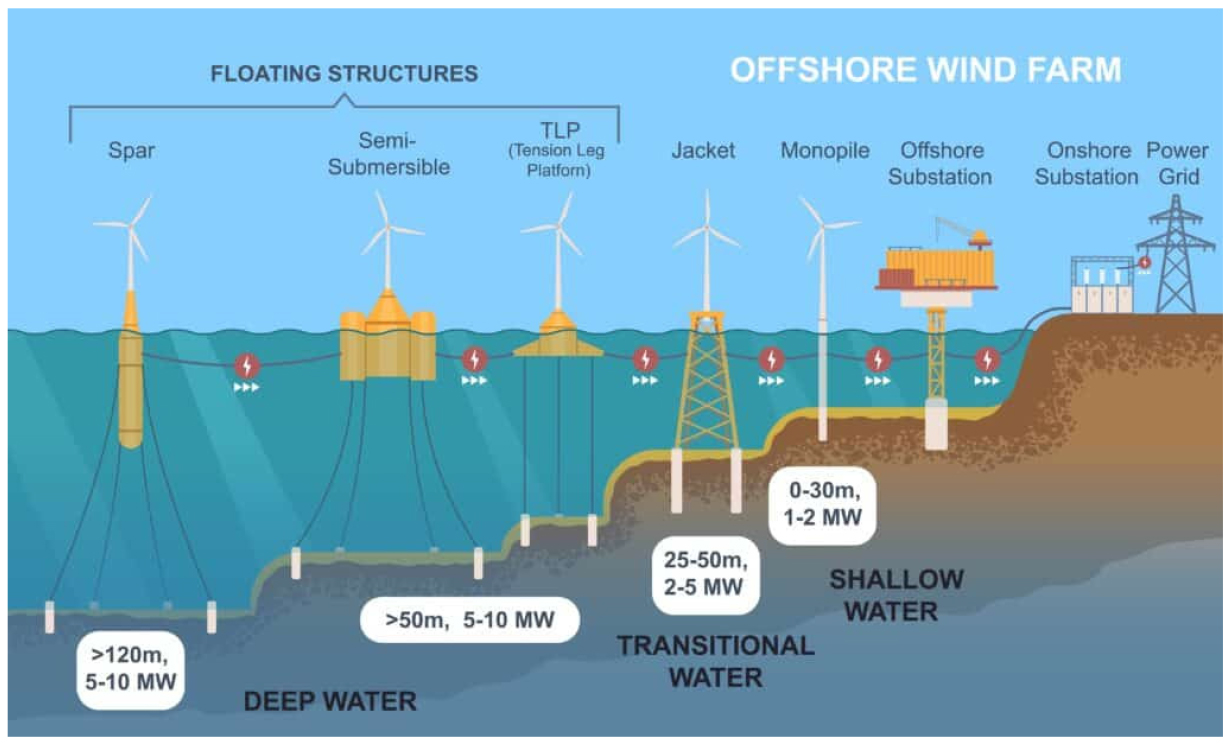
해상풍력단지는 설치 수심 및 구조물 형식에 따라 고정식(fixed-bottom)과 부유식(floating)으로 구분되며, 각각의 개발 환경은 지구물리탐사의 목적, 적용 장비, 요구되는 해상도 및 조사 범위 등에 영향을 미친다(Fig. 3). 이에 따라 탐사 환경별로 특화된 기술 사양과 기준을 구분하여 적용할 필요가 있다.

https://cdn.apub.kr/journalsite/sites/ggekseg/2025-028-04/N0540280405/images/ggekseg_2025_284_188_F3.jpg
Fig. 3

Offshore wind farm substructures (Sinay, 2024).

고정식 해상풍력단지

고정식 해상풍력 구조물은 일반적으로 수심 60 m 이내의 해역에 설치되며, 구조물 유형에 따라 요구되는 탐사 해상도 및 지질 정보의 세부 수준이 상이하다. 중력식 기초(0~15 m)는 단단하고 정리된 평탄한 지반에 설치되므로, 지지력 평가보다는 얕은 심도의 지반 분포와 밀도 특성 파악이 중요하다. 이에 따라 천부지층탐사기와 다중빔 음향측심기를 조합하여 표층지질 특성과 지형 변화를 분석하며, ISO 19901-8 에서는 수평 해상도 최소 150 m, 수직 해상도 0.2 m 이내가 권장된다(ISO, 2014). 모노파일(10~30 m)은 연암지반 또는 퇴적층 기반 위에 설치되며, 구조물 관입 깊이 평가와 불연속면 분석을 위해 다채널 탄성파탐사, 천부지층탐사기, 콘관입시험(cone penetration test, CPT)가 병행 적용된다. 특히, 수심 30 m 내외에서의 구조물 기초 안정성을 확보하기 위해 지층 경계 및 단층 탐지가 핵심이다. 국제적으로는 영국 Hornsea Project, 대만 Yunlin 프로젝트 등에서 모노파일 방식이 적용되었다. 재킷 및 트라이포드 구조물(20~50 m)은 연약지반에서 사용되며 구조물의 다리 지점 간 하중 분산 특성으로 인해 고정밀 2D/3D 탄성파탐사 및 ROV 기반의 영상 분석이 요구된다. 국내에서는 해상풍력발전단지 중 제주 탐라 해상발전단지와 서남해 해상풍력 실증단지에서 재킷 방식이 적용되었으며, 각각 30 MW, 60 MW의 발전 용량이 상업 운전 중이다(Ministry of Trade, Industry and Energy, 2025). 해상풍력발전단지 건설 전부터 운영 시까지 수심 측량과 해저지형 조사가 수행되었으며, OSIG (SUT) 및 ISO 19901-8, IHO S-44 기준에 따라 다중빔 음향측심기, 측면주사소나, 자력계, 천부지층탐사기가 각각 활용되었다(Netherlands Enterprise Agency, 2021; Yong et al., 2024). 이때 불균질한 지반 환경에서는 초고해상도 탄성파 탐사를 통해 불연속면, 기반암 심도, 연약층의 연속성 등을 파악하며, International Association of Oil & Gas Producers (2013)DNV (2012a) 기준이 탐사 깊이와 분해능을 규정한다(DNV, 2012a; International Association of Oil & Gas Producers, 2013; Terente et al., 2016).

부유식 해상풍력단지

부유식 해상풍력단지는 일반적으로 수심 60 m 이상의 해역에 설치되며, 해저면에 직접 고정되지 않고 실해역에서 스파형(spar), 반잠수식(semi-submersible), 바지형(barge), 그리고 장력지주식(tension leg platform, TLP)의 네 가지 안정화 메커니즘으로 유지된다(Edwards et al., 2023). 이에 따라 탐사의 목적은 구조물 하중 반응보다는 계류 안정성과 해저 위험 요소 탐지에 초점이 맞춰지며, 설계 및 검증 표준은 DNV (2012b)DNV (2018)에서 제시된 기준이 적용된다(DNV, 2012b; DNV, 2018). 부유식 해상풍력단지 개발에서는 정밀 지형 및 수심 모델 구축을 위해 다중빔 음향측심기가 사용되고, 측면주사소나 및 자력계를 활용한 천부지층 또는 초고해상도 탄성파 탐사를 통해 지층 연속성 및 불연속면 등을 해석한다(International Association of Oil & Gas Producers, 2013; Offshore Site Investigation and Geotechnics Committee, 2014). 최근에는 부유식 변전설비(floating substation)의 대형화 및 복합화에 따라 해저지형과 구조물 간의 간섭 영역을 정밀하게 해석하는 해저 지형 모델링 연구가 활발히 수행되고 있으며(Gillet et al., 2022), 고정밀 다중 센서 통합탐사의 중요성이 더욱 부각되고 있다. 그러나 국내에서는 고정식 해상풍력단지가 주로 설치되어 있어, 부유식 해상풍력발전단지 개발에 있어 국외에 비해 제한적이다(Ministry of Trade, Industry and Energy, 2025). ‘제11차 전력수급기본계획(2024~2038)’에 따르면 동해 가스전 설비를 활용하여 부유식 해상풍력을 중심으로 울산과 동남부 지역에 국내 해상풍력발전단지를 추진할 전망이므로(Ministry of Trade, Industry and Energy, 2025), 부유식 해상풍력발전단지 개발을 위한 해저 지형 조사 및 수심 측량, 천부지층탐사 등의 탐사 기준 수립이 필요한 실정이다.

해상풍력단지 개발을 위한 그라운드 모델링

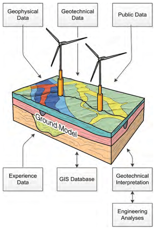
해상풍력단지의 기초 설계 및 부지 선정을 위해 해저 지반 조건에 대한 정밀한 해석과 평가는 필수적이다. 그라운드 모델링(ground modeling)은 해양 지구물리탐사 자료, 지반공학조사 결과, 실내시험 결과 등을 통합하여 공간적으로 일관된 지반 모델을 구축하는 과정을 의미하며, 해상풍력단지 개발 시 구조물의 기초 설계, 시공 리스크 평가, 공학적 해석의 기반이 된다. 그라운드 모델링 절차는 크게 네 가지로 구성되며, 이는 자료 수집 및 전처리, 자료 해석 및 통합, 그라운드 모델 구축, 그리고 설계 변수 예측 및 불확실성 평가로 진행된다. 이렇게 생성된 그라운드 모델은 Fig. 4와 같으며, 지질학적 기반 지식에 더하여, 지질, 지구물리, 지반공학 데이터를 통합하여 구성되어 지반 조건의 불확실성까지도 포함하여 표현한다.

https://cdn.apub.kr/journalsite/sites/ggekseg/2025-028-04/N0540280405/images/ggekseg_2025_284_188_F4.jpg
Fig. 4

Offshore wind turbine ground model (Shonberg et al., 2017).

ISO 19901-8 및 ISO 19901-10 기준에서는 해양 구조물 설계를 위한 지반모델 구축을 명시하고 있으며, 그라운드 모델은 해저면 및 해저하부의 구조, 물리적 특성, 지질 경계 및 잠재 위험 요소를 반영해야 한다. 국외 해상풍력단지 개발 프로젝트 중 Hornsea 프로젝트에서는 고해상도 탄성파 자료와 콘관입시험 및 보링 데이터를 통합한 3차원 지반모델을 활용하여 구조물 기초 설계와 단지 배치의 효율성을 극대화한 바 있다(SMart Wind, 2012; Terente et al., 2016). 이처럼 국내에서도 국제 기준을 반영한 표준화된 그라운드 모델 작성 지침의 수립이 필요한 실정이며, 이를 효과적으로 구현하기 위해서는 해양 지반 데이터베이스의 체계적 구축과 데이터 품질관리 체계 확립, 그리고 다중 센서 기반의 통합 해석 기법에 대한 기술 고도화가 병행되어야 한다.

결 론

해상풍력 발전이 세계적인 에너지 전환의 핵심으로 부상함에 따라 해양 지구물리탐사의 역할과 중요성도 증대되고 있다. 본 논문에서는 해상풍력단지개발을 위한 지반조사 관련 국제 기준과 주요 지구물리탐사 기법, 그리고 최신 탐사 장비 요구사항을 종합적으로 검토하였다. 국내에서도 해상풍력단지 조성이 활발히 논의되고 있으나, 해저 지질조사 측면에서는 국제적 추세에 비해 다소 초기 단계에 머물러 있다. 특히, 국내 해상풍력발전에 특화된 조사 지침이나 기준의 공백으로 인해 목적에 따라 서로 다른 국제 기준을 도입하고 있는 실정이다. 이로 인해 국내 해상풍력발전 조사 항목이나 성능 기준이 일관되지 않을 수 있으며, 현 시점의 산업 및 장비 등의 여건을 감안해야 되므로 국제 기준과 해외 장비 사양을 전면적으로 충족하기는 어렵다. 따라서 국내 해양풍력단지의 개발 여건에 부합하는 국내 조사 지침 및 기준을 수립하고, 해상풍력단지 개발의 핵심 구간에는 국제 기준에 합당한 정밀 조사를 수행하는 전략이 필요하다. 본 논문에서 정리한 국제 기준과 탐사 방법은 향후 국내 해상풍력발전단지 개발 목적의 지구물리탐사 기준 마련과 기술 표준화를 위한 기초 자료를 활용될 수 있을 것으로 기대된다.

Acknowledgements

본 연구는 중소기업청 사업인 창업성장기술개발사업(디딤돌)의 재원으로 중소벤처기업부의 지원을 받아 수행된 연구이며(RS-2024-00467500), 교육부와 부산광역시의 재원으로 지원을 받아 수행된 부산형 지역혁신중심 대학지원체계(RISE)의 연구결과 입니다(2025-RISE-02-002-012).

References

1

BloombergNEF, 2024, 1H 2024 Offshore Wind Market Outlook: Course Correct, https://about.bnef.com/insights/clean-energy/1h-2024-offshore-wind-market-outlook-course-correct/ (August 12, 2025 Accessed)

2

Carbon Trust, 2023,Unlocking the Potential: Challenges & Opportunities for the South Korean Offshore Wind Supply Chain, December 2023. (in Korean)

3

Chae, H., Jeong, S., Yeo, E. M., Chung, W., and Shin, S., 2025, Recent Advances in Geophysical Exploration for Offshore Wind Farm Development, J. Korea Inst. Mineral Mining Eng, 62(4), 425-438 (in Korean with English abstract).

10.32390/ksmer.2025.62.4.425
4

Chen, Y., and Lin, H., 2022, Overview of the development of offshore wind power generation in China, Sustain. Energy Technol. Assess., 53, 102766. https://doi.org/10.1016/j.seta.2022.102766.

10.1016/j.seta.2022.102766
5

Chet, H., 2025, Winds of Change: How Offshore Wind Boosts Taiwan-EU collaboration and Shapes Taiwan’s Climate Identity, https://taiwaninsight.org/2025/05/29/winds-of-change-how-offshore-wind-boosts-taiwan-eu-collaboration-and-shapes-taiwans-climate-identity/ (August 12, 2025 Accessed)

6

Corio, 2023, Geophysical Survey Vessel & Equipment Specifications, Rev. A (27 March 2023), Corio Generation.

7

DNV, 2012a, DNV-RP-C207: Statistical Representation of Soil Data, Det Norske Veritas, Høvik, Norway.

8

DNV, 2012b, DNV-RP-E301: Design and Installation of Fluke Anchors, Det Norske Veritas, Høvik, Norway.

9

DNV, 2018, DNV GL-ST-0119: Floating Wind Turbine Structures, Det Norske Veritas, Høvik, Norway.

10

DNV, 2024, Energy Transition Outlook 2024: A global and Regional Forecast to 2050, DNV, Høvik, Norway.

11

Edwards, E.C., Holcombe, A., Brown, S., Ransley, E., Hann, M., and Greaves, D., 2023, Evolution of floating offshore wind platforms: A review of at-sea devices, Renew. Sust. Energ. Rev., 183, 113416.

10.1016/j.rser.2023.113416
12

Energy and Space Co. offshore map, 2025, https://offshoremap.kr/ (November 27, 2025 Accessed)

13

Fugro, 2023, Operations and Processing Report – Fugro Pioneer 3D Seismic: Phase 4 3D UHRS Survey at the IJmuiden Ver Wind Farm Sites V and VI (IJ56), Dutch Sector, The Netherlands, https://offshorewind.rvo.nl/file/download/88a3da7e-cd18-4cf4-9308-02a5abf5d96d/ij56_20231219_fugro_gp-operations-and-processing-report-3d-uhrs-block.pdf (October 10, 2025 Accessed)

14

Gillet, M., Perrier, C., Marnay, D., Marketos, F., Kavuk, M., Yildiz, H., Stirl, T., and Boroomand, T., 2022, Design challenges for large offshore wind turbine transformers, Study Committee A2 – Power transformers & reactors, PS1 - Experience and new requirements for transformers for renewable generation, CIGRE Session 2022, 839.

15
16

Hill, A. W., Nicol, G., and Cook, M. R., 2024, A proposed standard seismic frequency nomenclature for geophysical site investigation surveys in the offshore energy sector, First Break, 42(11), 37-41.

10.3997/1365-2397.fb2024092
17

International Association of Oil & Gas Producers, 2013, Guidelines for the Conduct of Offshore Drilling Hazard Site Surveys, Report No. 373-18-1, OGP, London, UK.

18

International Energy Agency, 2023, World Energy Outlook 2023, https://iea.blob.core.windows.net/assets/ed1e4c42-5726-4269-b801-97b3d32e117c/WorldEnergyOutlook2023.pdf (August 12, 2025 Accessed)

19

International Energy Agency, 2024, World Energy Outlook 2024, https://www.iea.org/reports/world-energy-outlook-2024 (August 12, 2025 Accessed)

20

International Hydrographic Organization, 2020, S-44 Edition 6.1.0: Standards for Hydrographic Surveys, International Hydrographic Organization, Monaco.

21

ISO, 2014, ISO 19901-8: Petroleum and Natural Gas Industries — Specific Requirements for Offshore Structures — Part 8: Marine Soil Investigations, International Organization for Standardization, Geneva, Switzerland.

22

ISO, 2021, ISO 19901-10: Petroleum and Natural Gas Industries — Specific Requirements for Offshore Structures — Part 10: Marine Geophysical Investigations, International Organization for Standardization, Geneva, Switzerland.

23

Kongsberg, 2012, EM 2040 Multibeam Echosounder — Product Description, n.d., https://cdn1.shipserv.com/ShipServ/pages/profiles/54162/documents/EM-2040-Product-Description.pdf (Accessed October 30, 2025).

24

Lee, H. Y., Koo, N. H., Kim, B. Y., Kang, M. H., and Park, K. P., 2019, Status of marine seismic exploration technology, J. Korean Soc. Miner. Energy Resour. Eng., 56(1), 86-106, https://doi.org/10.32390/ksmer.2019.56.1.086 (in Korean with English abstract).

10.32390/ksmer.2019.56.1.086
25

McCoy, A., Musial, W., Hammond, R., Hernando, D. M., Duffy, P., Beiter, P., Pérez, P., Baranowski, R., Reber, G., and Spitsen, P., 2024, Offshore Wind Market report: 2024 Edition, National Renewable Energy Laboratory, Golden, CO, NREL/TP-5000-90525, https://www.nrel.gov/docs/fy24osti/90525.pdf

10.2172/2434294
26

Ministry of Economy, Trade and Industry, 2020, Vision for Offshore Wind Power Industry (1st), Japanese Government.

27

Ministry of Oceans and Fisheries, 2022, Implementation Plan for the Intelligent Maritime Traffic Information Service (2022), https://www.mof.go.kr/jfile/readDownloadFile.do?fileNum=1&fileType=MOF_ARTICLE&fileTypeSeq=45086 (October 10, 2025 Accessed) (in Korean).

28

Ministry of Trade, Industry and Energy, 2020, Offshore Wind Power Development Plan, https://www.korea.kr/common/download.do?fileId=197017860&tblKey=GMN (October 10, 2025 Accessed) (in Korean).

29

Ministry of Trade, Industry and Energy, 2025, The 11th Basic Plan for Electricity Supply and Demand (2024–2038), https://www.motir.go.kr/kor/article/ATCLc01b2801b/70152/view?mno=&pageIndex=1&rowPageC=0&schClear=on&startDtD=&endDtD=&searchCondition=1&searchKeyword=%EC%A0%84%EB%A0%A5%EC%88%98%EA%B8%89%EA%B8%B0%EB%B3%B8%EA%B3%84%ED%9A%8D# (August 12, 2025 Accessed) (in Korean).

30

Netherlands Enterprise Agency, 2021, Accelerating South Korean Offshore Wind through Partnerships, Netherlands Enterprise Agency, The Hague, The Netherlands.

31

Northland Power, 2020, Annual Report 2020, https://www.northlandpower.com/en/resources/Corporate%20Reports/NPI-AnnualReport-2020-FINAL_Feb%2022.pdf (October 10, 2025 Accessed)

32

Offshore Site Investigation and Geotechnics Committee (OSIG), 2014, Guidance Notes for the Planning and Execution of Geophysical and Geotechnical Ground Investigations for Offshore Renewable Energy Developments, Society for Underwater Technology, London, UK.

33

Shonberg, A., Harte, M., Aghakouchak, A., Brown, C. S. D., Andrade, M. P., and Liingaard, M. A., 2017, Suction bucket jackets for offshore wind turbines: Applications from in situ observations, Proc. TC209 Workshop, 19th International Conference on Soil Mechanics and Geotechnical Engineering, 65-77.

34

Sinay, 2024, What is Floating Wind?, https://sinay.ai/en/what-is-floating-wind/ (August 13, 2025 Accessed)

35

SMart Wind, 2012, Hornsea Project 2 Environmental Impact Assessment (Report No. UK06-060200-REP-0001), https://tethys.pnnl.gov/sites/default/files/publications/EIAHornsea2.pdf (November 18, 2025 Accessed)

36

Terente, V. A., Owen, M. J., Higgs, D. M., and Ellery, G., 2016, Derivation of ground models and characteristic geotechnical profiles in offshore wind farms at pre-FID stage, Int. J. Offshore Polar Eng., ISOPE-I-16-411.

37

Yong, S. B., Lim, E. P., Kim, H. W., Gwak, M. S., Kim, I. S., Jeon, I. S., and Kim, M. S., 2024, Scour depth analysis of foundation structure of southwestern sea offshore wind power demonstration complex, Wind Energy, 15(1), 69–81 (in Korean with English abstract).

10.33519/KWEA.2024.15.1.008
38

Yun, G. R., Lee, G. H., Ham, T. G., and Lee, G. H., 2011, Offshore wind turbine and geotechnical engineering, Geotech. Eng., 27(2), 8-17 (in Korean with English abstract).

페이지 상단으로 이동하기